Please review the following videos before getting started with this lab:
Materials and Equipment:
Materials:
Equipment:
Procedure:
***** This lab has to be implemented in both software (running simulations on Multisim) and hardware (using NI myDAQ) *****
Part A: Half wave rectification:
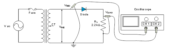
Figure 1
Software (Multisim):
Hardware (NI myDAQ):
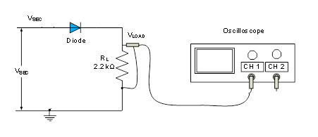
Figure 2
Review questions:
Deliverables:
Part B: Full wave rectification:
Software (Multisim):
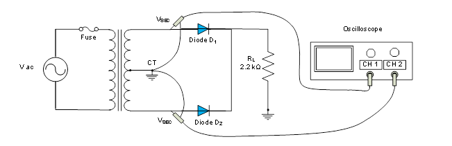
Figure 3
Hardware (NI myDAQ):
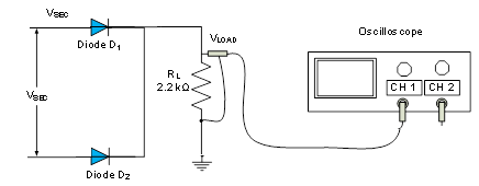
Figure 4
Review questions:
Deliverables:
Lab Report:
Grading Rubrics
Grading CriteriaPointsPart A: Half-wave rectifier circuit in Multisim – with and without filter capacitor10Part A: Half-wave rectifier circuit on NI myDAQ and breadboard with and without filter capacitor10Part A: Deliverables: Measurements and screen captures from Multisim and hardware15Review Questions10Part B: Full-wave rectifier circuit in Multisim – with and without filter capacitor10Part B: Full -wave rectifier circuit on NI myDAQ and breadboard with and without filter capacitor10Part B: Deliverables: Measurements and screen captures from Multisim and hardware15Review Questions10Report format (Proper use of template)10TOTAL100

Delivering a high-quality product at a reasonable price is not enough anymore.
That’s why we have developed 5 beneficial guarantees that will make your experience with our service enjoyable, easy, and safe.
You have to be 100% sure of the quality of your product to give a money-back guarantee. This describes us perfectly. Make sure that this guarantee is totally transparent.
Read moreEach paper is composed from scratch, according to your instructions. It is then checked by our plagiarism-detection software. There is no gap where plagiarism could squeeze in.
Read moreThanks to our free revisions, there is no way for you to be unsatisfied. We will work on your paper until you are completely happy with the result.
Read moreYour email is safe, as we store it according to international data protection rules. Your bank details are secure, as we use only reliable payment systems.
Read moreBy sending us your money, you buy the service we provide. Check out our terms and conditions if you prefer business talks to be laid out in official language.
Read more